Use a Nokia Serial Cable on an ARM9 Linkstation
From NAS-Central Buffalo - The Linkstation Wiki
Contents[hide] |
Introduction
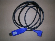
At the time of writing, clones of the DKU-5 and CA-42 data cables for Nokia mobile phones are the cheapest widely available (I purchased mine from ebay - they can be had for around $2.50 / €2 including postage!). Both should be electrically compatible with the Linkstation Pro (as well as other Linkstations, and the Linksys NSLU2 as well, and any other device which speaks the RS232 logical protocol with 3volt TTL electrical signal levels) - they incorporate a USB to RS232-3V transceiver (all the examples I've seen build the transceiver into a longer-than-usual USB "A" plug), and a Nokia "Pop-Port".
Means of connecting to the Linkstation Pro
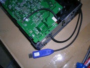
The illustrations here show the direct attachment of the cable to the main circuit board of the Linkstation Pro - it is also possible to use a friction-fit connector via the hole in the bottom of the case. Whilst in principle this sounds like a far nicer solution, a hacked-up USB "A" socket is not a good match for the pad spacing on the bottom of the linkstation, and it is quite easy to short between the contacts, or between a contact and the metal case. More than one person has broken the serial port on their LSPro as a result.
Old style 5.25 inch floppy drive edge-connectors work very well (no shorting problems - the connector spacing is correct), but they can be hard to find these days (I did see a few on ebay) and they are difficult to cut-down to the correct size. They are pretty much exclusive IDC style connectors, and soldering to them is fiddly. That having been said, you can then connect to any LS Pro without invalidating your warranty...
If you can't find a suitable 5.25" edge connector soldering directly to the Linkstation's board seems like the best solution. If you don't want your USB serial adaptor to be permanently connected, then a solder-on pin header is also a possibility, but it does have the disadvantage of requiring more parts, taking longer to construct, but still invalidating your warranty.
Preparing the Cable
What You Will Need
- Some soldering skills.
- Some means of determining continuity (e.g. a multimeter + hand-held probe leads).
- Some means of stripping insulated wires.
- A willingness to invalidate your warranty.
- A CA-42, or DKU-5 (some later Nokia phone cables e.g. the DKU-2, CA-53, CA-70 - which look similar are actually pure USB cables with no transceiver - DON'T use these, they won't work, and you might break your linkstation or USB port - you can tell because the USB plug is shorter, they are also a bit cheaper - if you want to double-check, use a multimeter to check whether the contacts of the USB "A" plug are connected directly to those of the pop-port).
- Suitable safety gear.
- Pliers, glue/tape, and volt meter (optional).
If you don't have all of these, then find someone who does. Maybe ask your local TV repair place to do the work (they'd probably be glad of the business).
Determining the wiring assignment of your cable
Several companies produce clones of the CA-42 and DKU-5 cables, unless you are very confident you know them already, it's necessary to determine which colour of wire in the cable maps to which signal assignment.
Cut and Strip Insulation from the Cable
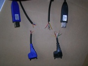
Cut the data cable about 60mm from the Nokia connector end, strip away approx 20mm of the outer sheath, and remove approx 3mm of insulation from each inner core.
The cables I bought were of two different designs, this may well vary from manufacturer to manufacturer.
- The RS232 transceiver is powered from the USB port, you only need to connect ground, data transmit, and data receive to the linkstation (this was my CA-42 cable, and had 3 wires).
- The RS232 transceiver is powered from the phone/Linkstation, as well as txd, rxd, and gnd, you also need to connect power (3.3v) to the linkstation board (this was my DKU-5 cable, and had 5 wires - an additional wire was used to signal what sort of cable was plugged into the phone (I think), and can be safely left disconnected).
Identify Each Wire
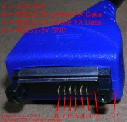
Establish which core is connected to which pin on the Nokia connector end (Nokia "pop port") using your continuity tester. The part of the "pin-out" which we care about are:
- pin 1 On both of the cables I used, pin 1 is actually missing (not needed with this design, so they didn't include it) it's the "other side" of the spring-clip from all the other pins).
- pin 2 On both of the cables I used, pin 2 is also missing (there is a space where it should be).
- pin 3 (normal length) connected to one of the wires on my DKU5, but not needed for the linkstation (isolate this wire)
- pin 4 (sticks out a bit further)+3.3v this is used to power the transceiver on the DKU-5 cable I have (red), but not the CA-42
- pin 5 (not connected)
- pin 6 (normal length) serial rxd - Data into phone/Linkstation green on DKU-5 blue
- pin 7 (normal length) serial txd - Data out from phone/Linkstation white on DKU-5 red
- pin 8 (sticks out a bit further) Signal Ground (gnd) black on dku5, orange on ca-42
- pin 9 to 14 not connected, and missing on both my connectors
On a piece of paper make a note of which colour wire was attached to each pin.
Sanity Check Your Findings
Check signal voltage levels for USB-powered designs (this won't work yet for device-powered designs, as you need to provide power to them for them to work).
If your cable does not connect to pin 3 (power from device), then at this point, it's probably wise to check the voltage generated by the adaptor:
- Make sure none of the bared wires are touching, and plug the adaptor into your PC.
- Fire up a terminal emulator, and connect it to the correct port (e.g. /dev/ttyUSB0 on Linux, you'll need to use the driver that came with the adaptor on Windows).
- Use a volt meter to verify the voltages between i. txd and gnd and ii. rxd and gnd. Neither voltages should exceed about 3.4v.
- Set your terminal emulator to use no hardware, or software flow control.
- Type some stuff into your terminal emulator (nothing should happen, but the voltage on the phone rxd pin should sag slightly as the bits are transmitted - press and hold a key on the keyboard to test).
- Connect together rxd and txd (just twisting them together is fine), and type some more. The characters which you see should appear back in the terminal window... Congratulations, you have just made a "loop back cable", and you have got the pin assignments correct.
- Exit your terminal emulator, and unplug the cable from your PC.
Connecting directly to the Linkstation Pro
Open up your Linkstation Pro - I have the v2 hardware undo the two screws at the back, and slide the side panel off.
CAUTION - high voltages are present in the power supply, and may be present even after the device is disconnected from the mains. Don't touch anything in the power supply area!
CAUTION - beware of sharp edges, wear gloves.
CAUTION - soldering is dangerous, there is a risk of inhaling toxic fumes (carcinogens and sensitisers) as well as burning yourself. Take adequate precautions.
Work out a way of getting the cable into the Linkstation - I slid it in through the "Kensington Lock" slot at the back, perversely, the 5 wire cable went in quite easily, but the 3 wire CA-42 was thicker, and more difficult. Flatten the cable slightly with a pair of pliers as you push it into the slot. If the cable isn't a tight fit, you should secure it to something inside the Linkstation at a later point (e.g. using a tie-wrap), to stop it being accidentally pulled out - this can damage the cable as the steel edge of the Kensington slot is sharp.
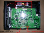
Locate the serial header
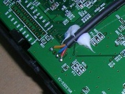
Identify the holes in the circuit board where the serial signals are made available (see photo).
Connect the Cable
Pull sufficient cable into the Linkstation to reach the serial header. With the board still screwed in, and the serial header at the bottom, the holes (from left to right) are:
- Ground - connect this to the wire that was connected to pin 8 of the Nokia pop port
- +3.3v - connect this to the wire that was connected to pin 4 of the Nokia pop port
- rxd (data into Linkstation) - connect this to the wire that was connected to pin 6 of the Nokia pop port
- txd (data out of Linkstation) - connect this to the wire that was connected to pin 7 of the Nokia pop port
Don't poke too much bare copper through the holes, or you'll touch the grounded steel of the chassis and cause a short-circuit once the device is powered on, 3 mm of bare copper seemed to be enough. Find some way of holding the cable in place while you solder the connectors - I used a couple of dabs of hot-melt glue, but you could try some strong tape, or a willing assistant.
If you are using a cable which uses the device-powered transceiver design, then you may wish to initially connect just gnd, and +3.3v to the cable, and then wire rxd and txd together (and isolate with some tape). Replace the cover and screws, and power-up the linkstation, your terminal emulator should then behave as a "loop-back" and characters which you type should be echoed back to you - see the #Sanity_Check_Your_Findings section.
Using your continuity tester, verify that none of +3.3v, rxd, or txd are shorted to gnd.
Try it Out
Replace the cover, plug the USB A connector into your PC, fire up your terminal emulator at 115200 baud, 8n1, no flow control, and power-up your Linkstation...
Tip: if your output is unreadable, try to set your emulator at 57600 baud, it works for me ....
